StackMatch, Mini StackMatch General Information
Array Solutions StackMatch, StackMatch II, StackMatch II Plus, and Mini StackMatch
Key Benefits of Both the StackMatch and Mini-StackMatch
- Easy hook-up, no complex relay switch networks or carefully cut phase lines
- Works with Tri-band and Multi-band antennas as well as Mono-band antennas
- Allows user to steer take-off angles of the stack as well as double beam in two or three directions.
- Stacking antennas adds considerable GAIN and cleans up the pattern.
- BIP-BOP (Both in Phase, Both out of Phase) Can be easily achieved for two Mono-Band or multi-band antennas
- Two Feed line Option allows a second radio to utilize 1 beam in a stack of beams when needed.
- The StackMatch System now used by over 5,000 stacks around the world!
Why trust your stacking system to copy cat products? Go with the best proven reliable solution. That is why we offer the original Array Solutions lifetime warranty. Built tough and now with over 5,000 in service, you know they are the best!
These guys can take it even in New England, Canadian, Northern EU, and in the brutal arctic circle winters. They also beat the heat and moisture down in the tropics. Get a StackMatch, the gold standard! Trusted by contesters around the world!
The regular StackMatch is designed to stack, match and power split to one, two or three antennas. But if you just want two antennas see the StackMatch II description below.
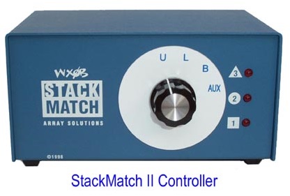
Rotary LED Controller
It will provide the user with all combinations of antenna selection. In a typical three high mono-band or tri-band Yagi stack this would be represented by looking at the dial on the control box or of course its much easier to just look at the LEDs and see what antennas are being selected.
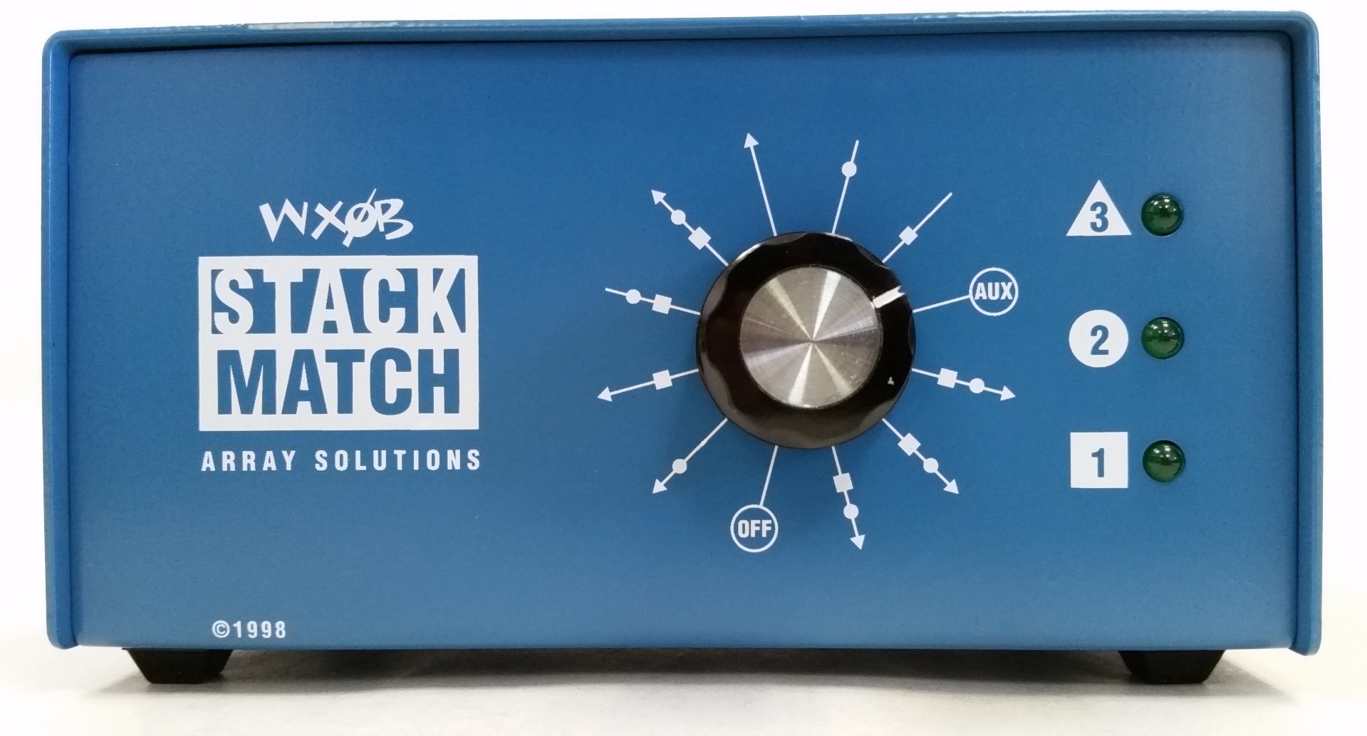
Added to the switch is an "AUX." auxiliary position. It is used to select the dual feed line option or our new 180 degree phase shifter. With the dual feedline option a second radio can pull a single antenna out of the stack and make a contact. Then the antenna can be returned to the stack by rotating the switch back to normal stack operation. If the 180 degree phase shifter option is used the Aux position will switch it in and your stack will generate high angle radiation for E-skip propagation to allow you to work close in stations. Any of these options can be added to an existing StackMatch stack.
The StackMatch defaults to the no power position of ALL antennas selected. This means that in case of a 12V failure, you still have all the antennas selected.
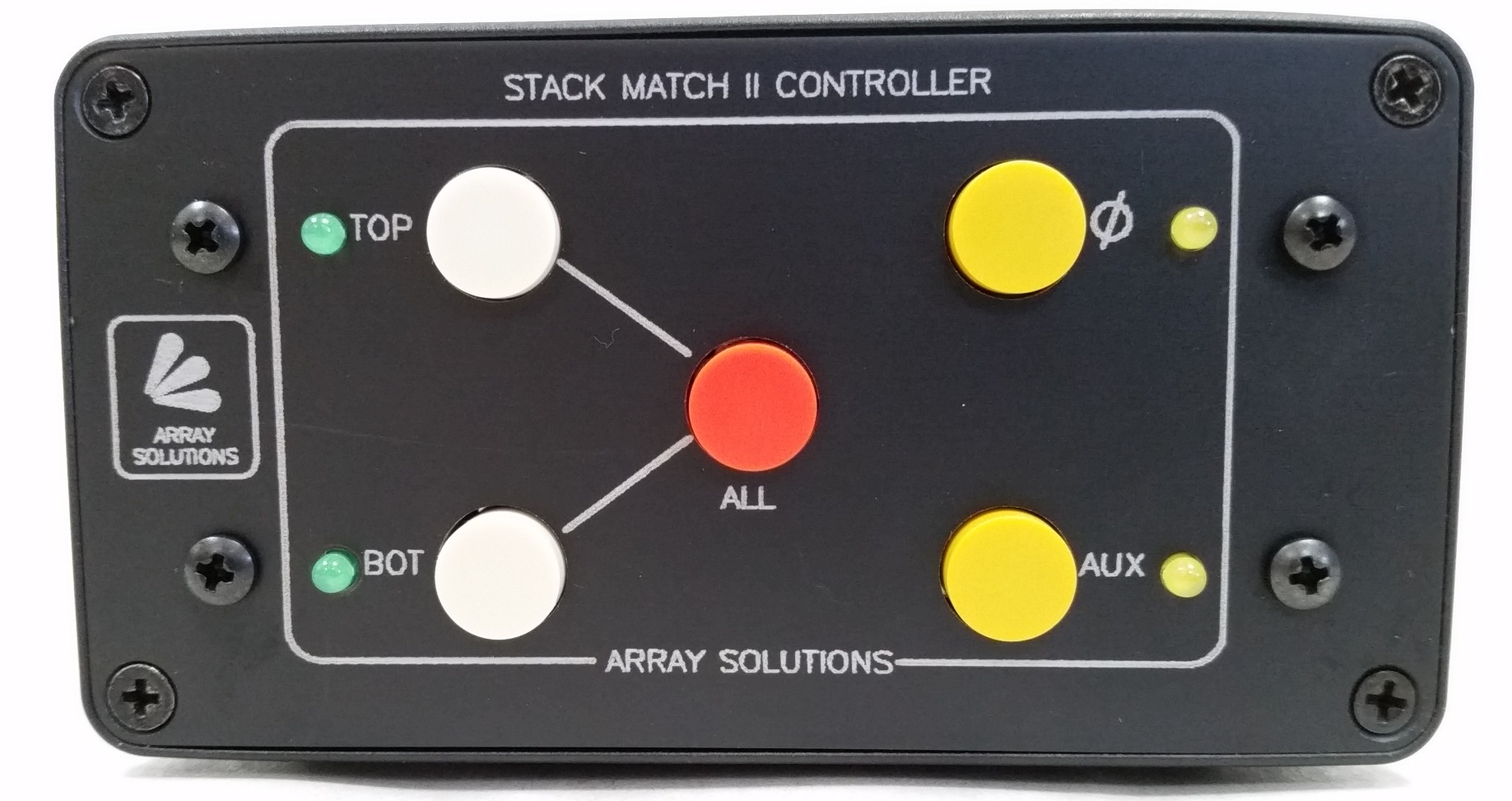
Push Button Controller
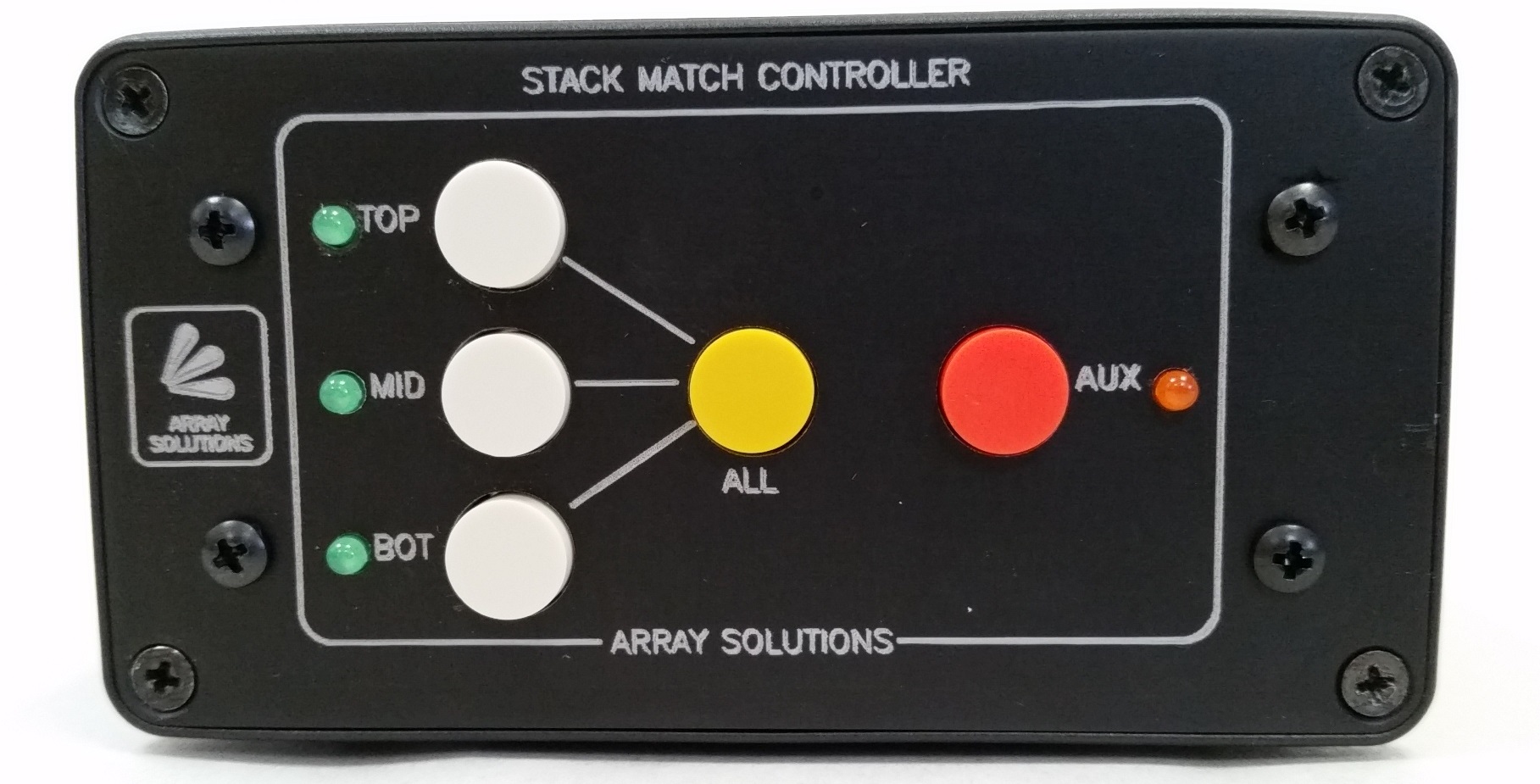
This is the new dual mode StackMatch firmware. Hold in the AUX button for 3 seconds and release to toggle the mode. Push On/Push Off mode is indicated by flashing the TOP and AUX LEDs 3 times and the new multi-select mode is indicated by flashing the MID and AUX LEDs 3 times. The mode is also shown at power up. Also, the TX configuration is now saved in the EEPROM and will be loaded when the unit powers up. In multi-select mode (recommended) you select two antennas by pressing both of their buttons at the same time - top two, bottom two or even top & bottom! Press the ALL button and you're back to all 3!
Different Transmit Configurations!
What is this for? You might want to always transmit on all 3 antennas (for example) and vary how you receive. Connect PTT to the controller, and it's automatic! To set the TX stack configuration set the desired antennas as usual during Receive, then hold in the ALL button for longer than 2 seconds and release. The LEDs for the TX antennas will blink 3 times. You can now set the antenna for RX and when the PTT input is grounded it will switch to the TX configuration. To cancel separate TX/RX configurations, hold in the AUX button for over 2 seconds and release. The AUX LED will blink 3 times indicating TX mode cancelled.
The StackMatch is unique in that it does not rely on 1/4 wave phasing lines to accomplish the match to the antennas, instead the user only has to feed each antenna with EQUAL lengths of coaxial cable. The antennas can be mono-band Yagis, multi-band Yagis, single or multi-band quads, or vertical arrays (see StackMatch for Verticals). For diversity transmission and reception a combination of antennas can be accomplished, such as a Yagi and a vertical.
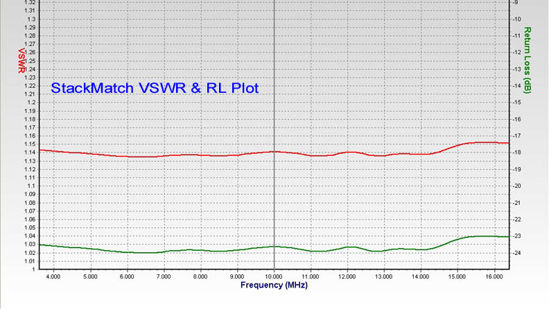
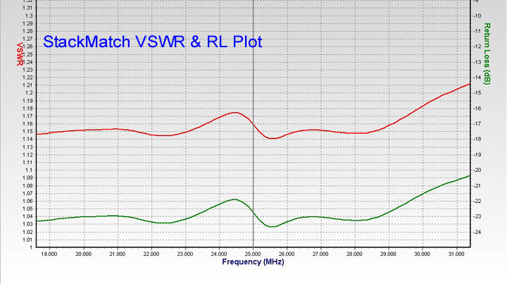
The StackMatch operates from 1.8 through 30 MHz and is rated at 3 kW CW. Below are typical VSWR and Return Loss plots of a StackMatch & StackMath II from 3.5 - 31.5 Mhz.
StackMatches are built using strip line PCBs and sealed relays to deliver this kind of performance. VSWR is the red line read from the left and return loss is the green line. The measurements are made using 50 ohm dummy loads, you will see a 1.0:1 VSWR in the band with real antennas since they are reactive. These plots are typical of all StackMatch products.
Advantages of a Three Antenna Stack
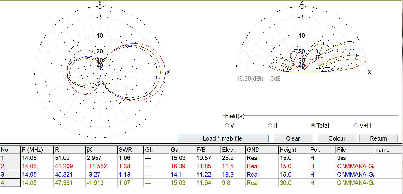
A stack of three Antennas allows any of the seven combinations for 1, 2 or 3 antennas, vertically shaping the radiation lobes and changing the radiation take-off angle to optimize the signals depending on the varying ionospheric propagation angles. To understand what happens, lets analyze a stack of three five element Yagi-Uda antennas for 20 meters. The antennas are at 15, 30 and 45 m (50, 100 and 150 ft) high.
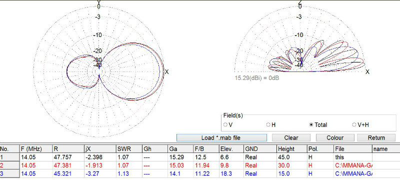
When the antenna at the 15 m (50 ft) level is used, there is a main lobe centered around 18 degrees and a deep null at 45 degrees elevation above the horizon.
When the antenna at the 30 m (100 ft) level is used, there are two main lobes, at 10 and 32 degrees and deep nulls near 20 degrees and 45 degrees of elevation above the horizon.
When the antenna at the 45 m (150 ft) level is used, there are three main lobes at 7, 21 and 36 degrees and deep nulls at 14, 28 and 46 degrees.
This shows that one antenna at one height will not cover all the incoming angles that vary through the day depending on the ionospheric propagation conditions.
Now, let's explore the combinations of selecting two antennas in phase out of a stack of three and also when the three antennas are selected at the same time.
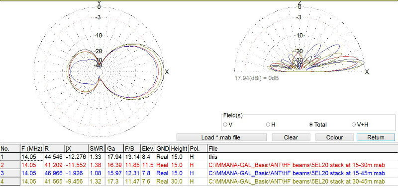
There are four possible combinations when using more than one antenna at the time:
StackMatch II
Two Antennas switch for upper/lower/Both in phase selections
StackMatch II PLUS
5 kW model only - Same features as the StackMatch II but also has a built in 180 degree phase shifter in the remote relay box to give you upper/lower/BIP-BOP (Both In Phase/ Both Out of Phase) selections.
The LEDs and the switch displays the antennas selected, Upper, Lower, Both, as well as the Aux "OUT OF PHASE" option. An Array Solutions exclusive function that not only works for mono band antennas but will also work for Tribanders, multibanders, log periodic, quads, delta loops and verticals.
Advantages of a Two Antenna Stack
Stack of two antennas allows any of the three combinations for upper/lower/both antennas, vertically shaping the radiation lobes and changing the radiation take-off angle to optimize the signals depending on the varying ionospheric propagation angles. Let us analyze a two five element Yagi-Uda antennas stack at 15 and 30 m high.

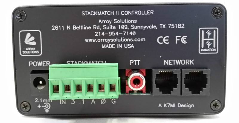
Specifications for Both StackMatch and StackMatch II
Control voltage: 12-16 V DC 80 mA, max
RF power rating: HF - 3 kW CW, 6 meters 2 kW CW
Frequency: HF & 6 m, 1.8 to 30 MHz or 7 to 60 MHz (6 meter model)
Case: Metal weather-resistant case with galvanized U bolt.
Warranty: Lifetime - except for lightning and we may fix that too!
Why be an amateur? - Get a real StackMatch!
To download the StackMatch II Manual, click here
To download the StackMatch Manual, click here
Click here to download the SM PB-3 (StackMatch Push Button controller for three antennas) manual